



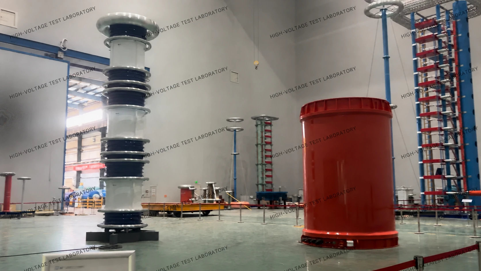
Reactor Loss Meausring System
The entire test system employs a control method that combines a computer with a PLC. The PLC is primarily used to configure the logical relationships between components, integrate and execute low-level action commands, and implement basic system protection functions. It offers advantages such as flexible programming, high reliability, and fast execution speeds. Meanwhile, the industrial control computer is primarily used to organize the test process, issue action commands, and implement advanced system protection functions. It communicates with the PLC via wireless transmission, The two are completely isolated from one another, which effectively prevents interference with communication signals and ensures the safety of the computer in the event of a test specimen’s ground discharge.
The test system uses variable-frequency drive control to enable multi-speed regulation—including fast and slow rates—of voltage ramp-up and ramp-down during performance testing, thereby achieving finer voltage and current control and more precise data sampling capabilities.
Test data can be accurately measured using a standard capacitor in conjunction with a dielectric loss bridge to determine the loss data of the reactor at different frequencies.
Functions
It primarily employs the principle of a current comparator, which gives it high ratio accuracy and stability in measurements, making it suitable for measuring the capacitance and tangent of the loss angle (tgδ) of high-voltage power equipment—such as power cables, high-voltage bushings, power capacitors, reactors, transformers, and other high-voltage power equipment, as well as the dielectric constant (ε) and tangent of the loss angle (tgδ) of various solid or liquid insulating materials. It can also measure the ratio error and phase angle error of high-voltage transformers or voltage transformers.